Quick start guide
In order to see working the PMOD-Lora you have to register the device on the activity website using your personal account. After the registration login and you will access the main page.
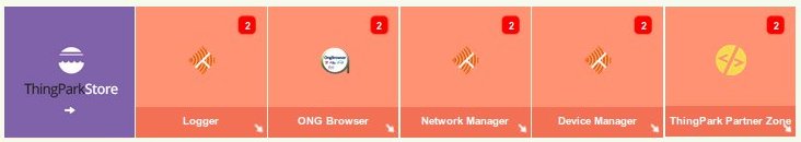
First up we have to register your Microchip RN2483 device, to do this, click on Device Manager arrow to open a new window.
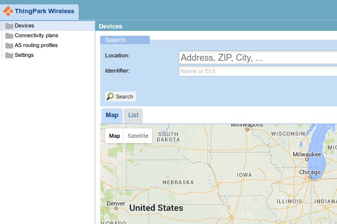
Click the right mouse button on the Devices folder and select + Create.
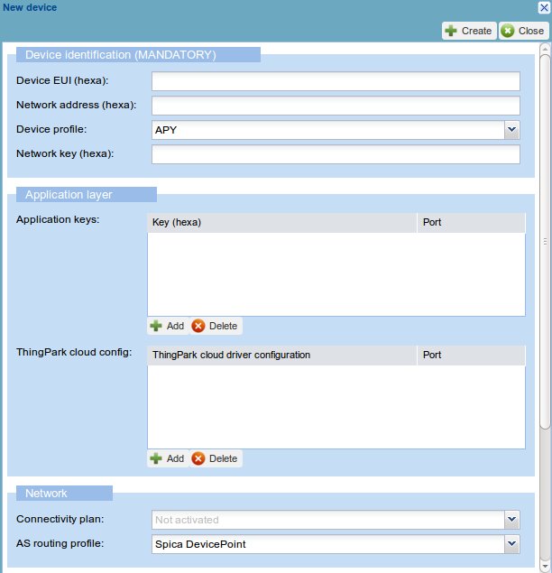
In this form you have to insert the data we have stored in the RN2483. The following fields are mandatory:
- Device EUI: the 16-hex identification key of the device. It is unique for every device, you can read it on the label of the board as in the image. For example the code can be 0004A30B001B9954
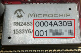
- Network address: last 4 less significant bytes from the Device EUI key, for example if the code is 0004A30B001B9954 then the network address will be 001B9954
- Device profile: LoRaWAN 1.0 class A
- Network key (hexa): we have already saved it in the RN2834 device, it is the Device EUI key copied twice, for example if the device EUI is 0004A30B001B9954 then the network key you have to insert will be 0004A30B001B99540004A30B001B9954.
- Application keys: Insert AFBECD56473829100192837465FAEBDC, port 4. We have saved it in the RN2834 device. Press “Update” button to confirm.
- Connectivity plan: choose yours
Optional field but useful:
- Name: insert a name just to recognize your device.
Then click on the top right + create.
Warning
If some key is wrong then the device will be unable to send data correctly in the Lora network.
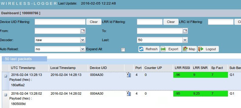
After the registration, you can close the window device manager and on the main page go to Logger.
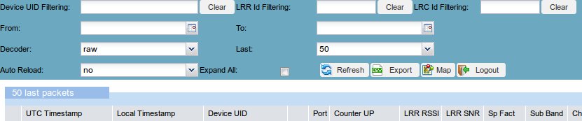
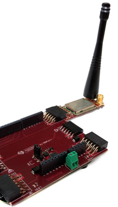
Here you will see all the messages sent by your device. Now take the FRDM-KL26Z board and connect it to the RSR1066 board. It is required mount the strip connectors:
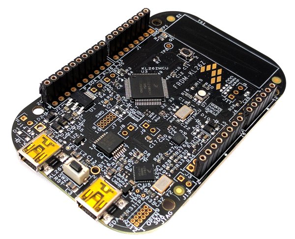
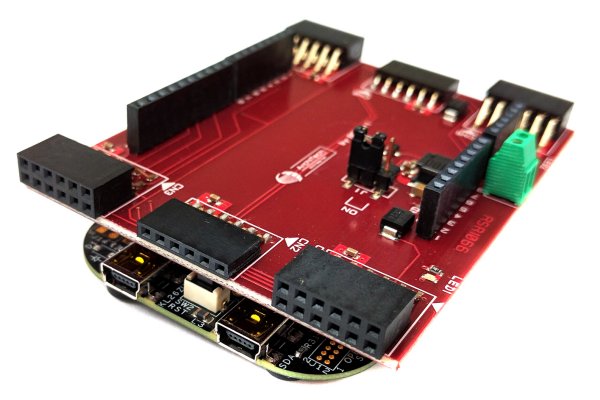
Connect the PMOD module to the CN7
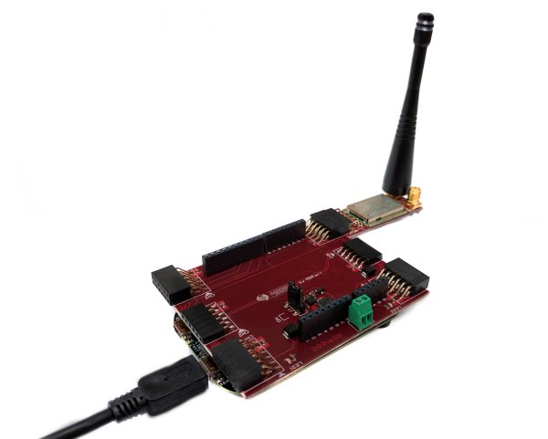
Then power supply the FRDM board via mini USB connection.
The board will send messages every 30 seconds. Now it’s time to see the data sent. Power off the board. And in the logger window, you will have 2 rows, every row is a message received from the server. If you click on the + node you can see the unencrypted data received Payload (hex):. All messages start with the number 18, the other three number couples are the data read from the accelerometer mounted on the board. You will see the data changed when you have tilted the board and sent the second message.